FIELD MULTIMETER » MX-202 «
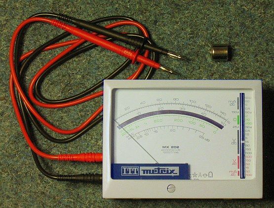
This "small/BIG-SCALE" MultiMeter is a "Classic": No large central switch to
change ranges - instead it has a thumb-wheel on the right side and a vertical
"Radio Scale" ( with rope & winch ) on the right side. The A-Ω-V Scales cover
the whole front of the 140 x 105 x 50 mm3 ( 5_1/2" x 4" x 2" ) instrument.
M U L T I M E T E R » MX-202 « by ITT-METRIX, Paris / France (1975)
******************************************************************************
Class 1.5 (DC) & 2.5 (AC) ; 40 kΩ / Volt (DC) & 1 kΩ / Volt (AC)
< Ri(I) = 2 kΩ >
50 mV .. 500 V ; 25 μA .. 0.5 A & 1000 V / 5 A DC Ranges
15 V .. 500 V ; 50 μA .. 0.5 A & 1000 V / 5 A AC Ranges
(x1) .. 20kΩ , (x10) .. 200kΩ , (x100) .. 2MΩ ;
w. 1.35 V SPECIAL BATTERY »RM-1R« MALLORY Cell
Because of its stability, NO ZERO-Ω-CALIBRATION is necessary!
0 dB .. +25 dB ( as Difference Measurement )
(1.) The FUSE-"Repair" is quick & easy ( see DETAIL Picture on the left ) ...
(1.)  (2.) (2.) 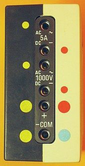 The ORANGE SQUARE covers a little SPOOL with a very thin 0.05 mm Ø SILVER-WIRE.
Pull it out of the SLOT and mount it between the 2 SCREWS over the "WINDOW".
(2.) A T T E N T I O N :
-------------------------
DC & AC uses the same plugs for "Normal Ranges" - only the "Extended Ranges"
uses the + 1000 V (DC)/(AC) or + 5 A (DC)/(AC) Plugs - The SELECTOR has to be
set either on DC or AC-Range. As a reminder, I put COLOR-MARKS beside the plugs
BLUE / RED, red, red ; YELLOW / YELLOW, yellow, yellow. ( See right picture )
In these cases there is N O F U S E PROTECTION as shown in the DIAGRAM ...
The ORANGE SQUARE covers a little SPOOL with a very thin 0.05 mm Ø SILVER-WIRE.
Pull it out of the SLOT and mount it between the 2 SCREWS over the "WINDOW".
(2.) A T T E N T I O N :
-------------------------
DC & AC uses the same plugs for "Normal Ranges" - only the "Extended Ranges"
uses the + 1000 V (DC)/(AC) or + 5 A (DC)/(AC) Plugs - The SELECTOR has to be
set either on DC or AC-Range. As a reminder, I put COLOR-MARKS beside the plugs
BLUE / RED, red, red ; YELLOW / YELLOW, yellow, yellow. ( See right picture )
In these cases there is N O F U S E PROTECTION as shown in the DIAGRAM ...
|

                              ... The components are mounted on a PRINT-BOARD.

(3.)  MODIFICATION  for  1.5 Volt  B A T T E R Y   R E P L A C E M E N T   ...
******************************************************************************
|
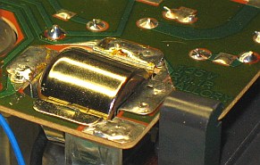 |
1.35 V MALLORY Batteries
are no longer available.
1.5 V REPLACEMENTS
( e.g. »PX1« or »LR50« )
have the same size,
BUT ...
|
|
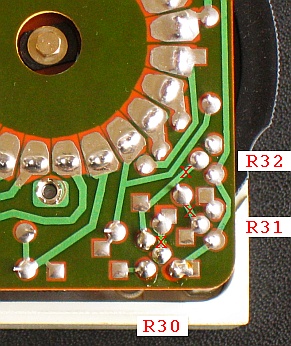
The higher 1.5 V  Battery needs MODIFICATIONS OF THE WIRING, because ZERO-OHM
has to be in the CALIBRATION RANGE. The easiest way are ADDITIONAL RESISTORS,
between the TRIM-POTS: (x1)R30 = 50 Ω ; (x10)R31 = 500 Ω  & (x100)R32 = 5 kΩ.
The left picture shows (X) were the printed connections have to be cut ...


... HOW TO FIND THE RIGHT RESISTORS ?
=====================================
(a) CUT the printed connections on (X) with a sharp knife
(b) Solder "TEST-WIRES" at the open points
(c) Set the (x1), (x10) & (x100) TRIM-POTS to CENTER POSITION
(d) Place the  1.5 V  BATTERY in the holder ( see picture above )
(e) SHORT-CUT the input plugs
(f) Set SELECTOR to (x1), (x10) & (x100) and ...
(g) ... connect (e.g.)  HELIPOTS  to the "Test-Wires"
(h) The right  V A L U E S  are found, when the INDICATOR shows ZERO OHM ...

    (x1) R'30 = + 33 Ω ;  (x10) R'31 = + 330 Ω ,  (x100) R'32 = + 3.3 kΩ

(i) Remove HELIPOTS & "Test-Wires" and solder RESISTORS in place ...
    ( COLOR-CODES:  [orange/orange/black],  [or./or./brown]  & [or./or./red] )

                     ... The right picture above shows the final modification.
Suggestion:
-----------
Dependent on its usage,  it may be convenient to drill  3 small holes into the
case to allow  ZERO-Ω-CALIBRATION  without opening the  MX-202.

impressum:
******************************************************************************
© C.HAMANN             http://public.BHT-Berlin.de/hamann             02/15/13
... HOW TO FIND THE RIGHT RESISTORS ?
=====================================
(a) CUT the printed connections on (X) with a sharp knife
(b) Solder "TEST-WIRES" at the open points
(c) Set the (x1), (x10) & (x100) TRIM-POTS to CENTER POSITION
(d) Place the 1.5 V BATTERY in the holder ( see picture above )
(e) SHORT-CUT the input plugs
(f) Set SELECTOR to (x1), (x10) & (x100) and ...
(g) ... connect (e.g.) HELIPOTS to the "Test-Wires"
(h) The right V A L U E S are found, when the INDICATOR shows ZERO OHM ...
(x1) R'30 = + 33 Ω ; (x10) R'31 = + 330 Ω , (x100) R'32 = + 3.3 kΩ
(i) Remove HELIPOTS & "Test-Wires" and solder RESISTORS in place ...
( COLOR-CODES: [orange/orange/black], [or./or./brown] & [or./or./red] )
... The right picture above shows the final modification.
Suggestion:
-----------
Dependent on its usage, it may be convenient to drill 3 small holes into the
case to allow ZERO-Ω-CALIBRATION without opening the MX-202.
impressum:
******************************************************************************
© C.HAMANN http://public.BHT-Berlin.de/hamann 02/15/13
|