previous <<==>> next
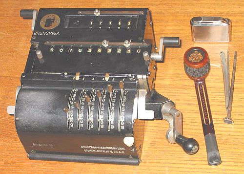
BRUNSVIGA-10
The smallest » BRUNSVIGA « ever made
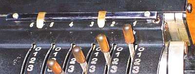
The (upper) DECIMAL MARKER and the INPUT CLEAR KEY were missing
and had to be home made - Remarks to RESTORATION see below ...
TECHNICAL DATA of the Mechanical Calculator BRUNSVIGA-10
*************************************************************************
Serial-Number: 138576
Dimensions: (ca.) Width = 8_3/4" / 22 cm
Depth = 7 " / 18 cm
Height = 3_1/2" / 9 cm
Weight: (ca.) 8 lbs / 3.5 kg
Mechanics: Split-Stepped Drum
Functions: Add, Subtract, Multiply, Divide
Registers: Input = 6 Decimals
Counter = 5 Decimals (Neg.Figures RED)
Arithmetic = 10 Decimals
Manufacturer:
BRUNSVIGA MASCHINENWERKE
GRIMME, NATALIS & CO. A.-G.
Braunschweig
Germany
1935
BASICS & HOW TO USE the BRUNSVIGA-10
****************************************
BASIC SETTINGS:
===============
(a) Main-Crank:
---------------
For addition (+) the crank is turned clockwise; for subtraction (-) the
crank is turned counter-clockwise. In the idle position the crank is DOWN
& LOCKED. To make one or more turns with the crank, pull out the handle to
unlock. When finished the turn(s), let the handle snap into lock again. The
locked down position only makes other functions (ex. clearing) accessible.
REMARK: Every started turn has to be finished completely!
Accidentally started turns are correctible somehow.
(b) Clearing Registers:
-----------------------
The input
has to be cleared by pressing the right lever on front
The counter unit
will be cleared with the crank on the upper left side
The arithmetic register
will be cleared with the crank on the right side of the carriage
(c) Shifting the Carriage:
--------------------------
The carriage can be pulled out to the right by hand. Pressing down either
the left or right silver lever, let the carriage move one step to the left.
The left position "1" is the "Start Position" of the carriage.
(d) Counting Direction:
-----------------------
After clearing the counter, a white mark shows its neutral state. It
depends of the 1st turn of the main crank what happens: When (for
addition) the 1st turn is clockwise, the counter shows white figures;
when (for subtraction) the 1st turn is counter-clockwise, the counter
shows red figures. In both cases the counter will work with 10s-carry
and allows "Shortened Method of Multiplication".
ADDITION & SUBTRACTION:
=======================
Example: 123 + 45 - 6 = 162
Clear input, counter and arithmetic units.
ADD: Enter the first number (123) in the far right of the input unit.
Make a positive (clockwise) turn with the crank to transfer the number
into arithmetic unit. The counting unit displays the figure 1. Enter the
second number (45). Make a positive (clockwise) turn with the crank to
add the number. The arithmetic unit displays the intermediate sum (168)
and the counting unit displays the figure 2.
SUBTRACT: Enter the third number (6). Make a negative (counter-clockwise)
turn with the crank. The arithmetic unit displays the result (162) and
the counting unit is decreased by 1.
REMARK: NEGATIVE RESULTS are displayed in the arithmetic unit
as the COMPLEMENT of the next higher 10, 100, 1000, ...
Example: -12 = 99...9988
MULTIPLICATION:
===============
Example: 123 x 45 = 5535
Clear input, counter and arithmetic units.
Enter the multiplicand (123) in the far right of the input unit. The
multiplicator (45) has two digits, so the carriage is shifted to
position 2. Make positive (clockwise) turns with the crank, until the
first figure of the multiplicator (4) will appear in the 2nd position of
the counter unit. Shift the carriage to position 1. Repeat positive
turns with the crank, until the second figure of the multiplicator (5)
appears in the 1st position of the counter unit. The multiplication is
done: The multiplicand (123) stays in the input unit, the multiplicator
(45) in the counter and the result (5535) is in the arithmetic unit.
DIVISION:
=========
Example: 22 : 7 = 3.1428 Remainder 4
Division requires 3 steps:
(1st) To Set the Dividend into Arithmetic Unit:
-----------------------------------------------
For the maximum number of decimals, pull out the carriage to the far
right position. Enter the dividend (22) in the far right of the input
unit. Make a positive (clockwise) turn with the crank to transfer
into arithmetic unit.
(2nd) To Set the Divisor into Input Unit:
-----------------------------------------
Clear counter & input units.
Enter the divisor (7) under the dividend (22).
(3rd) To Divide:
----------------
Make negative (counter-clockwise) turns with the crank until the
arithmetic unit shows an "underflow". Make one positive (clockwise)
turn with the crank. Move the carriage to the next left position.
Repeat this procedure until the required number of decimals ...
The result (3.1428) is in the counter (in RED), and the remainder (4)
is in the arithmetic unit. The divisor (7) stays in the input unit,
therefore an additional decimal can be estimated...
( 5, cause 5 x 7 = 35).
Have a look at "Calculating Trickies" ...
R E M A R K S :
=========================================================================
Remark to History:
|
 ------------------
The calculator came in bad shape - found in a dumpster ??? Dirty, rusty,
bent and dent ... If the machine could tell their story, it would be an
interesting one !! The inventory tag reads:
BUNDESGESUNDHEITSAMT / ROBERT KOCH INSTITUT
Remarks to Restoration:
-----------------------
(1)
After cleaning, the machine could NOT RESET TO ZERO properly, because the
worn-out mechanics. To prevent that the RESET COMB on the axle of the
ARITHMETIC UNIT snaps in its PARK-POSITION-GAP just before all figures
are reset to zero ...
------------------
The calculator came in bad shape - found in a dumpster ??? Dirty, rusty,
bent and dent ... If the machine could tell their story, it would be an
interesting one !! The inventory tag reads:
BUNDESGESUNDHEITSAMT / ROBERT KOCH INSTITUT
Remarks to Restoration:
-----------------------
(1)
After cleaning, the machine could NOT RESET TO ZERO properly, because the
worn-out mechanics. To prevent that the RESET COMB on the axle of the
ARITHMETIC UNIT snaps in its PARK-POSITION-GAP just before all figures
are reset to zero ...
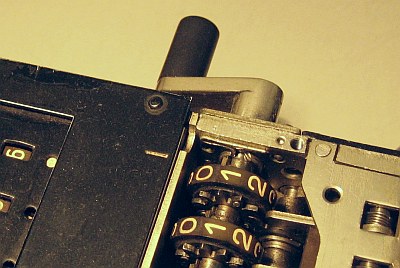 The SHOWN STATE is just before the finish: The CLEAR-Crank is to turn
counter-clockwise! The RESET COMB is LEFT of the GAP. THE TIP OF A WIRE
(glued-in on top of the right side) guards the worn-out edge of the park
position GAP - makes it sure, that the COMP drives over it - before it
fall into the GAP (as designed !).
(2)
The input decimal marker bar was missing. A new INPUT MARKER BAR with
MARKERS out of brass sheet is home-made ...
The SHOWN STATE is just before the finish: The CLEAR-Crank is to turn
counter-clockwise! The RESET COMB is LEFT of the GAP. THE TIP OF A WIRE
(glued-in on top of the right side) guards the worn-out edge of the park
position GAP - makes it sure, that the COMP drives over it - before it
fall into the GAP (as designed !).
(2)
The input decimal marker bar was missing. A new INPUT MARKER BAR with
MARKERS out of brass sheet is home-made ...
 (3)
The BELL was not active. Because the hammer is not to adjust in working
conditions, the central hole in the bell was made oval: Now the bell is
adjustable in hight relative to the hammer until the sound is right.
(3)
The BELL was not active. Because the hammer is not to adjust in working
conditions, the central hole in the bell was made oval: Now the bell is
adjustable in hight relative to the hammer until the sound is right.