PULSAR + COUNTER = DIGITAL TIMER
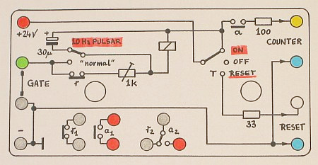
The Wire Diagram ( on the back side) of the 10 Hz Pulsar ...
Have a look at the 1 Hz Modification !
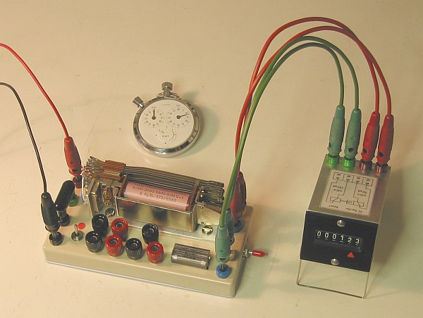
Start / Stop either manual by SWITCH or remote by GATE
                Back to the COUNTER Main Page

» H O W   T H E   P U L S A R   R E L A Y   I S   W O R K I N G «
=================================================================
The right switch ( with the red cap ) has 3 positions: The middle
is "OFF".  When pushed in its down position, the " R E S E T " in
the  C O U N T E R  is activated.  When released it switches back
by itself in the middle position. The upper position is "ON".

When the power is switched "ON",  the parallel capacitor "steals"
the current from the relay until the capacitor is charged. ( This
time we name "T-ON". )  Than the relay get active:  It closes the
active contact  "a"  and opens the rest contact  "r".   With this
opening,  the relay is cut-off from its power source - but it get
the discharge current from the capacitor  to hold the contact "a"
until the capacitor is discharged. ( This time we name "T-OFF". )
Now the rest contact  "r"  get closed and the cycle starts again.

With a capacity of 30 μF together with a 1 kΩ  tunable resistance
we make the relay to pulse 10 times/second (= 10 Hz ) on 24 Volt.
With the active contact "a" the counter get the "+1"-PULSE ...

When the 10Hz / "normal" SWITCH is set to "normal", the capacitor
is disconnected and the resistor is bridged and has no effect. In
this case the relay can be used ( Red-Cap-Switch = ON )  in other
applications with its contact group  "r1", "a1"  &  "r2/a2" ...

Have a look at  A N O T H E R   R E L A Y   A P P L I C A T I O N

            » How A Telephone Dial System Works ... «

impressum:
*******************************************************************
© C.HAMANN       http://public.BHT-Berlin.de/hamann        08/10/10
|