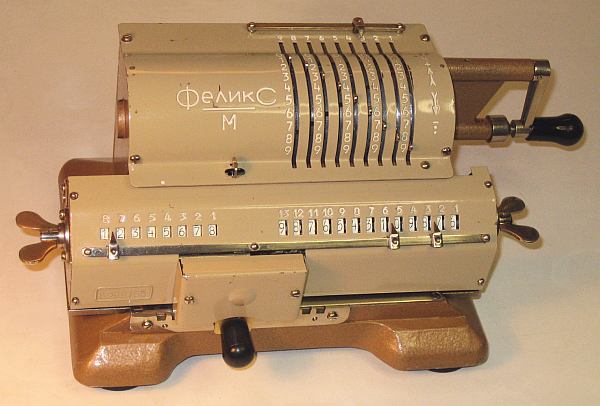
TECHNICAL DATA of the Mechanical Calculator F E L I K S » Model M «
****************************************************************************
( milk-chocolate-coloured )
Serial Number: E299755
Dimensions: (ca.) Width = 11 " / 28 cm
Depth = 6 " / 15 cm
Height = 5_1/4 " / 13 cm
Weight: (ca.) 8 lbs / 3.6 kg
Mechanics: Pin-Wheel / Sprossenrad
10s Carry Mechanism
Counter Stepping Mechanism + Animation
Functions: Add, Subtract, Multiply, Divide
Registers: Input = 9 Decimals
Counter = 8 Decimals ( NO 10s-Carry; WHITE ONLY )
Arithmetic = 13 Decimals
Manufacturer:
 Moscow / USSR
1970
H O W T O U S E the FELIKS Model M
******************************************
BASIC SETTINGS:
===============
(a) Crank:
----------
For addition (+) the crank is turned clockwise; for subtraction (-) the
crank is turned counter-clockwise. In idle position the crank is down &
locked. To make one or more turns with the crank, pull out the handle
to unlock. When finished the turn(s), let the handle snap into the lock
again. The locked down position only makes other functions accessible.
REMARK: Every started turn has to be finished completely!
Accidentally started turns are correctible somehow.
(b) Clearing Registers:
-----------------------
Procedure to clear the input:
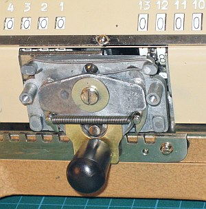
Shifting the LEVER in the middle ( under M ) to the left will close
the lower ends of the "input-slots". Turn the crank clockwise until
all input-levers are reset because of this new barrier in the "input-
slots". Than turn the crank COUNTER-CLOCKWISE (!) to idle position
and shift the LEVER back to the right.
The counter unit
will be cleared with the WING-NUT on the LEFT SIDE of the carriage
The arithmetic register
will be cleared with the WING-NUT on the RIGHT SIDE of the carriage
(c) Shifting the Carriage:
--------------------------
Pushing the BLACK KNOB on front to the LEFT or RIGHT will move the
carriage one step left or one step right. When the BLACK KNOB is lifted,
the carriage can be moved continuously right or left by hand.
The left position "1" is the "Start Position" of the carriage.
ADDITION & SUBTRACTION:
=======================
Example: 123 + 45 - 6 = 162
Clear input, counter and arithmetic units.
ADD: Enter the first number (123) in the far right of the input unit.
Make a positive (clockwise) turn with the crank to transfer the number
into arithmetic unit. The counting unit displays the figure 1. Enter the
second number (45). Make a positive (clockwise) turn with the crank to
add the number. The arithmetic unit displays the intermediate sum (168)
and the counting unit displays the figure 2.
SUBTRACT: Enter the third number (6). Make a negative (counter-clockwise)
turn with the crank. The arithmetic unit displays the result (162) and
the counting unit is decreased by 1.
REMARK: NEGATIVE RESULTS are displayed in the arithmetic unit
as the COMPLEMENT of the next higher 10, 100, 1000, ...
Example: -12 = 99...9988
MULTIPLICATION:
===============
Example: 123 x 45 = 5535
Clear input, counter and arithmetic units.
Enter the multiplicand (123) in the far right of the input unit. The
multiplicator (45) has two digits, so the carriage is shifted to
position 2. Make positive (clockwise) turns with the crank, until the
first figure of the multiplicator (4) will appear in the 2nd position of
the counter unit. Shift the carriage to position 1. Repeat making positive
turns with the crank, until the second figure of the multiplicator (5)
appears in the 1st position of the counter unit. The multiplication is
done: The multiplicand (123) stays in the input unit, the multiplicator
(45) in the counter and the result (5535) is in the arithmetic unit.
DIVISION:
=========
Example: 22 : 7 = 3.1428571 Remainder 3
Clear input, counter & arithmetic units.
Division requires 3 steps:
(1st) To Set the Dividend into Arithmetic Unit:
-----------------------------------------------
For the maximum number of decimals, pull out the carriage to the far
right position. Enter the dividend (22) in the far right of the input
unit. Make a positive (clockwise) turn with the crank to transfer
into arithmetic unit.
(2nd) To Set the Divisor into Input Unit:
-----------------------------------------
Clear the counter.
Enter the divisor (7) above the dividend (22).
(3rd) To Divide:
----------------
Make negative (counter-clockwise) turns with the crank until the
arithmetic unit shows an "underflow". Make one positive (clockwise)
turn with the crank. Move the carriage to the next left position.
Repeat this procedure until the required number of decimals ...
The result (3.1428571) is in the counter unit ( in RED ), and the
remainder (3) is in the arithmetic unit. The divisor (7) stays in the
input unit, therefore an additional decimal can be estimated ...
( 4, cause 4 x 7 = 28).
Have a look at "Calculating Trickies" ...
( * ) HOW TO REMOVE THE CARRIAGE FOR M A I N T E N A N C E
************************************************************
Moscow / USSR
1970
H O W T O U S E the FELIKS Model M
******************************************
BASIC SETTINGS:
===============
(a) Crank:
----------
For addition (+) the crank is turned clockwise; for subtraction (-) the
crank is turned counter-clockwise. In idle position the crank is down &
locked. To make one or more turns with the crank, pull out the handle
to unlock. When finished the turn(s), let the handle snap into the lock
again. The locked down position only makes other functions accessible.
REMARK: Every started turn has to be finished completely!
Accidentally started turns are correctible somehow.
(b) Clearing Registers:
-----------------------
Procedure to clear the input:
Shifting the LEVER in the middle ( under M ) to the left will close
the lower ends of the "input-slots". Turn the crank clockwise until
all input-levers are reset because of this new barrier in the "input-
slots". Than turn the crank COUNTER-CLOCKWISE (!) to idle position
and shift the LEVER back to the right.
The counter unit
will be cleared with the WING-NUT on the LEFT SIDE of the carriage
The arithmetic register
will be cleared with the WING-NUT on the RIGHT SIDE of the carriage
(c) Shifting the Carriage:
--------------------------
Pushing the BLACK KNOB on front to the LEFT or RIGHT will move the
carriage one step left or one step right. When the BLACK KNOB is lifted,
the carriage can be moved continuously right or left by hand.
The left position "1" is the "Start Position" of the carriage.
ADDITION & SUBTRACTION:
=======================
Example: 123 + 45 - 6 = 162
Clear input, counter and arithmetic units.
ADD: Enter the first number (123) in the far right of the input unit.
Make a positive (clockwise) turn with the crank to transfer the number
into arithmetic unit. The counting unit displays the figure 1. Enter the
second number (45). Make a positive (clockwise) turn with the crank to
add the number. The arithmetic unit displays the intermediate sum (168)
and the counting unit displays the figure 2.
SUBTRACT: Enter the third number (6). Make a negative (counter-clockwise)
turn with the crank. The arithmetic unit displays the result (162) and
the counting unit is decreased by 1.
REMARK: NEGATIVE RESULTS are displayed in the arithmetic unit
as the COMPLEMENT of the next higher 10, 100, 1000, ...
Example: -12 = 99...9988
MULTIPLICATION:
===============
Example: 123 x 45 = 5535
Clear input, counter and arithmetic units.
Enter the multiplicand (123) in the far right of the input unit. The
multiplicator (45) has two digits, so the carriage is shifted to
position 2. Make positive (clockwise) turns with the crank, until the
first figure of the multiplicator (4) will appear in the 2nd position of
the counter unit. Shift the carriage to position 1. Repeat making positive
turns with the crank, until the second figure of the multiplicator (5)
appears in the 1st position of the counter unit. The multiplication is
done: The multiplicand (123) stays in the input unit, the multiplicator
(45) in the counter and the result (5535) is in the arithmetic unit.
DIVISION:
=========
Example: 22 : 7 = 3.1428571 Remainder 3
Clear input, counter & arithmetic units.
Division requires 3 steps:
(1st) To Set the Dividend into Arithmetic Unit:
-----------------------------------------------
For the maximum number of decimals, pull out the carriage to the far
right position. Enter the dividend (22) in the far right of the input
unit. Make a positive (clockwise) turn with the crank to transfer
into arithmetic unit.
(2nd) To Set the Divisor into Input Unit:
-----------------------------------------
Clear the counter.
Enter the divisor (7) above the dividend (22).
(3rd) To Divide:
----------------
Make negative (counter-clockwise) turns with the crank until the
arithmetic unit shows an "underflow". Make one positive (clockwise)
turn with the crank. Move the carriage to the next left position.
Repeat this procedure until the required number of decimals ...
The result (3.1428571) is in the counter unit ( in RED ), and the
remainder (3) is in the arithmetic unit. The divisor (7) stays in the
input unit, therefore an additional decimal can be estimated ...
( 4, cause 4 x 7 = 28).
Have a look at "Calculating Trickies" ...
( * ) HOW TO REMOVE THE CARRIAGE FOR M A I N T E N A N C E
************************************************************
 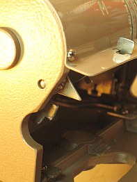 (1st) Remove the CARRIAGE-LOCK from bottom
(2nd) To be able to slight-out the carriage to the right,
open the GAP ON THE LEFT SIDE and UNHINGE the "Stop-Lever"
(3rd) Now the "Counter-Finger" can pass the gap:
LIFT & HOLD the BLACK KNOB and slide the carriage to the right
( ** ) R E M A R K S T O R E S T O R A T I O N ...
============================================================================
(1st) The three right input digits were locked. It was found: "ZINC-PEST",
a "Disease" what let the metal expand under special circumstances.
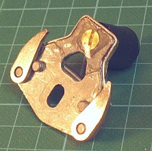
(2nd) The black knob to move the cariage left or right was broken/missing.
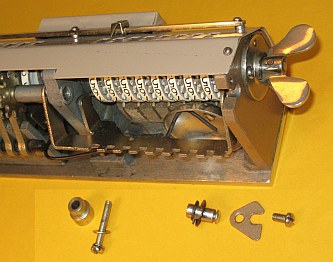
START: Dismounting the PINWHEEL CYLINDER ( Observe many tiny parts !)
by removing both SideWalls with 2 x 3 Screws from the Bottom ...
(1st) Remove the CARRIAGE-LOCK from bottom
(2nd) To be able to slight-out the carriage to the right,
open the GAP ON THE LEFT SIDE and UNHINGE the "Stop-Lever"
(3rd) Now the "Counter-Finger" can pass the gap:
LIFT & HOLD the BLACK KNOB and slide the carriage to the right
( ** ) R E M A R K S T O R E S T O R A T I O N ...
============================================================================
(1st) The three right input digits were locked. It was found: "ZINC-PEST",
a "Disease" what let the metal expand under special circumstances.
(2nd) The black knob to move the cariage left or right was broken/missing.
START: Dismounting the PINWHEEL CYLINDER ( Observe many tiny parts !)
by removing both SideWalls with 2 x 3 Screws from the Bottom ...
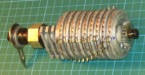 After turning the BIG NUT, the axle end got free and the right pin-wheels
could be separated, dismantled & filed - until functionality was restored.
See DETAILS of the PIN-WHEELS
To re-mount a BLACK KNOB ( eg. a drawer's knob ), also the "infected board"
had to be treated: The cracks had to be reinforced with a glued-on sheet of
brass on front and additional with a steel-wire glued around its edges ...
After turning the BIG NUT, the axle end got free and the right pin-wheels
could be separated, dismantled & filed - until functionality was restored.
See DETAILS of the PIN-WHEELS
To re-mount a BLACK KNOB ( eg. a drawer's knob ), also the "infected board"
had to be treated: The cracks had to be reinforced with a glued-on sheet of
brass on front and additional with a steel-wire glued around its edges ...
  After assembling: Finally all works well again!
impressum:
****************************************************************************
© C.HAMANN http://public.BHT-Berlin.de/hamann 03/16/13
After assembling: Finally all works well again!
impressum:
****************************************************************************
© C.HAMANN http://public.BHT-Berlin.de/hamann 03/16/13
|