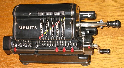
MELITTA VI / 16
Have a Look at the WORKSHOP (B): MELITTA_IV/16
Have a Look at the MELITTA_VII/16
T E C H N I C A L D A T A of the Mechanical Calculator MELITTA VI/16
***************************************************************************
Serial Number: 120064
Dimensions: (ca.) Width = 12 " / 30 cm
Depth = 5_1/2" / 14 cm
Height = 6 " / 15 cm
Weight: (ca.) 9_1/2 lbs / 4.3 kg
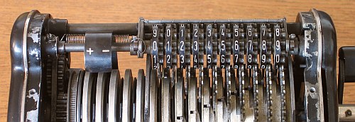
Mechanics: Pin-Wheel / Sprossenrad
10s Carry Mechanism
Functions: Add, Subtract, Multiply, Divide
Registers: Input = 10 Decimals
Counter = 8 Decimals
Arithmetic = 16 Decimals
Manufacturer:
FORTUNA WERK
Suhl / Thueringen
( GDR ) Germany
1960
H O W T O U S E the MELITTA VI/16
*****************************************
BASIC SETTINGS:
===============
(a) Crank:
----------
For addition (+) the crank is turned clockwise; for subtraction (-) the
crank is turned counter-clockwise. In the idle position the crank is DOWN
& LOCKED. To make one or more turns with the crank, pull out the handle to
unlock. When finished the turn(s), let the handle snap into lock again. The
locked down position only makes other functions (ex. clearing) accessible.
REMARK: Every started turn has to be finished completely!
Accidentally started turns are correctible somehow.
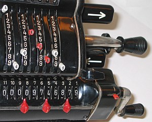
(b) Shifting the Carriage:
--------------------------
With the ARROW KEYS the carriage will move one step to the LEFT or RIGHT.
Pushing the BLACK KNOB on front allow the carriage to be moved by hand
continuously right or left.
The left position "1" is the "Start Position" of the carriage.
(c) Clear Input:
----------------
Moving the BLACK LEVER up will reset the input to 0000000000.
(d) Clear Counter and Arithmetic Units:
---------------------------------------
Unusual: CLEARING needs TWO(2)TURNS of the carriage's crank.
Pushing the build-in lever in the crank's shaft allow 3 axial positions:
In the far left position only the counter unit will be cleared.
In the middle position counter & arithmetic units will be cleared.
In the far right position only the arithmetic unit will be cleared.
(e) Counting Direction:
-----------------------
The counting direction (+/-) will be set by shifting the lever behind
the crank's base: The actual state of shifting left (-) or right (+)
is displayed on top behind a round window. In case of (+) the counter
& arithmetic unit are working in the same direction; in case of (-)
both are working opposite. In both cases the counter is working
with 10s-carry - and allows "Shortened Method of Multiplication".
ADDITION & SUBTRACTION:
=======================
Example: 123 + 45 - 6 = 162
Clear input, counter and arithmetic units; set carriage to position 1.
ADD: Enter the first number (123) in the far right of the input unit.
Make a positive (clockwise) turn with the crank to transfer the number
into arithmetic unit. The counting unit displays the figure 1. Enter the
second number (45). Make a positive (clockwise) turn with the crank to
add the number. The arithmetic unit displays the intermediate sum (168)
and the counting unit displays the figure 2.
SUBTRACT: Enter the third number (6). Make a negative (counter-clockwise)
turn with the crank. The arithmetic unit displays the result (162) and
the counting unit is decreased by 1.
REMARK: NEGATIVE RESULTS are displayed in the arithmetic unit
as the COMPLEMENT of the next higher 10, 100, 1000, ...
Example: -12 = 99...9988
MULTIPLICATION:
===============
Example: 123 x 45 = 5535
Clear input, counter & arithmetic units.
Enter the multiplicand (123) in the far right of the input unit. The
multiplicator (45) has two digits, so the carriage is shifted to
position 2. Make positive (clockwise) turns with the crank, until the
first figure of the multiplicator (4) will appear in the 2nd position of
the counter unit. Shift the carriage to position 1. Repeat making positive
turns with the crank, until the second figure of the multiplicator (5)
appears in the 1st position of the counter unit. The multiplication is
done: The multiplicand (123) stays in the input unit, the multiplicator
(45) in the counter and the result (5535) is in the arithmetic unit.
DIVISION:
=========
Example: 22 : 7 = 3.1428571 Remainder 3
Clear input, counter & arithmetic units.
Division requires 3 steps:
(1st) To Set the Divisor into Input Unit:
-----------------------------------------
Enter the DIVISOR (7) in the far right of the input unit.
(2nd) To Set the Dividend into Arithmetic Unit:
-----------------------------------------------
For the maximum number of decimals, pull out the carriage to the far
right. Set the DIVIDENT (22) into the arithmetic unit with the
affiliated toothed wheels appropriately under the divisor.
(3rd) To Divide:
----------------
Set counting direction to (-) via switch behind crank. Make negative
(counter-clockwise) turns with the crank until the arithmetic unit
shows an "underflow". Make one positive (clockwise) turn with the
crank. Move the carriage to the next left position. Repeat this
procedure until the required number of decimals ...
The result (3.1428571) is in the counter unit, and the remainder (3)
is in the arithmetic unit. The divisor (7) stays in the input unit,
therefore an additional decimal can be estimated...
( 4, cause 4 x 7 = 28).
Set counting direction back to (+) via switch behind crank
Have a look at "Calculating Trickies" ...
R E M A R K S T O R E S T O R A T I O N :
==========================================================================
The calculator came blocked, nothing worked. (1st) Fixing obvious things:
Cleaning the inside & oiling. Replaced missing springs on the input reset
lever and the input display unit. (2nd) The crank was blocked, because
the LEFT-SHIFT OF THE INPUT-DISPLAY could not be completed. A "SENSOR
LEVER" ( active when the crank starts turning ) seemed to be worn-out.
S O L U T I O N : An ADDITIONAL SPRING ( with just the right force ! )
was mounted between display unit and left side ...
|
 (3rd) Input values shown on display where different to the number of set
( visible ) sprockets. It is possible to RE-ADJUST the wrong set INPUT
LEVERS when the crank is turned half: Than there is space for adjustments.
(3rd) Input values shown on display where different to the number of set
( visible ) sprockets. It is possible to RE-ADJUST the wrong set INPUT
LEVERS when the crank is turned half: Than there is space for adjustments.
|
    (4th)
    Replaced missing caps
    with pieces of colored
    insulation pipes ...
|
impressum: ************************************************************************** © C.HAMANN http://public.BHT-Berlin.de/hamann 02/22/18 |