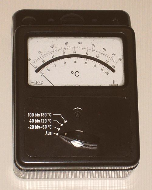
... It starts with this dumped ( analog ) ELECTRICAL THERMOMETER with lost sensor.
Because the high-sensitive SIEMENS 20 μA INSTRUMENT is OK, an I D E A came up ...
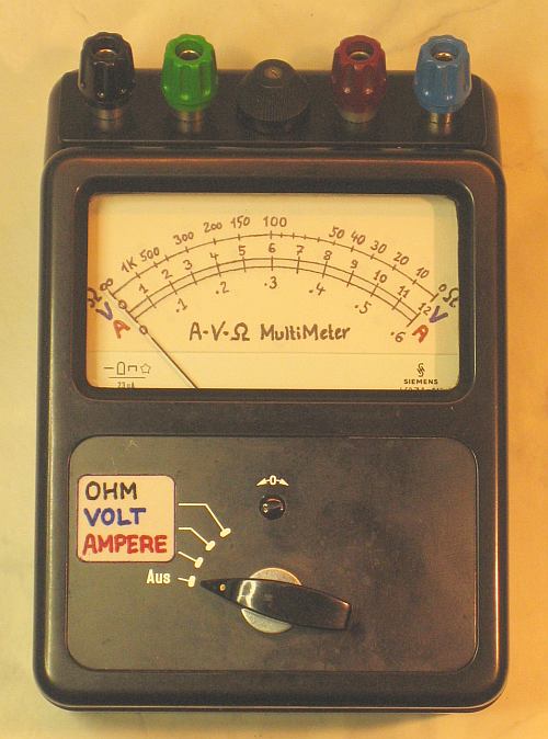
Make a P R O J E C T WITH KIDS - Build a » A-V-Ω MULTI-METER « out of it!
===================================================================================
(A) P L A N N I N G :
**********************
Use the existing switch for 3 Ranges ...
( _ ) OFF
(1st) 12 Volt
(2nd) 600 Milli-Ampere
(3rd) Ohm ( with 1.5 V BATTERY in box on back side )
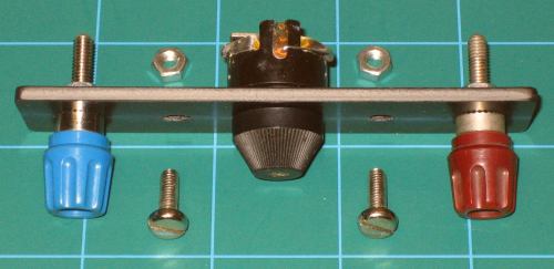
On the empty top a T E S T board with PLUGS & POTI will be installed ...
 How the 20 μA instrument looks INSIDE ...
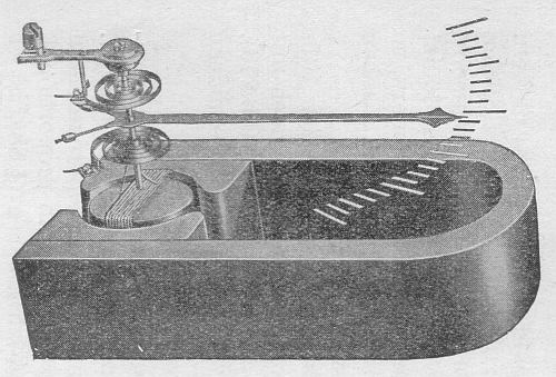 The current in the little spool generates a magnetic field, what interact with the
magnetic field of the permanent magnet to a torque of the axle. The 2 spirals are
both contacts of the spool and provide the counter-moment. The torque is readable
via arrow on the scale and proportional to the value of the current in the spool.
R E M A R K S :
===============
In the F O R M S the LETTERS U, I, R refer to Voltage, Current & Resistance.
Their U N I T S are VOLT (= V ), AMPERE (= A ) & OHM (= Ω ).
(1st) The VOLT Range:
---------------------
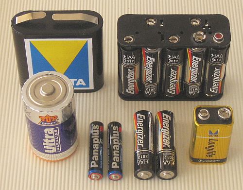
Common used batteries are 1.5 V types, as »AAA«, »AA« & »MONO« Cells,
4.5 V & 9 V - Blocks and "combined" 12 V - Blocks or CAR BATTERIES ...
The current in the little spool generates a magnetic field, what interact with the
magnetic field of the permanent magnet to a torque of the axle. The 2 spirals are
both contacts of the spool and provide the counter-moment. The torque is readable
via arrow on the scale and proportional to the value of the current in the spool.
R E M A R K S :
===============
In the F O R M S the LETTERS U, I, R refer to Voltage, Current & Resistance.
Their U N I T S are VOLT (= V ), AMPERE (= A ) & OHM (= Ω ).
(1st) The VOLT Range:
---------------------
Common used batteries are 1.5 V types, as »AAA«, »AA« & »MONO« Cells,
4.5 V & 9 V - Blocks and "combined" 12 V - Blocks or CAR BATTERIES ...
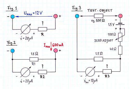
 With "OHM's LAW" we calculate the (Serial-)RESISTOR (= R ) for a 12 V MAX-Range ...
U = R * I ==> R = U / I = 12 V / 20 μA = 600 kΩ
Refer to Fig. 1 in the following sketch ...
With "OHM's LAW" we calculate the (Serial-)RESISTOR (= R ) for a 12 V MAX-Range ...
U = R * I ==> R = U / I = 12 V / 20 μA = 600 kΩ
Refer to Fig. 1 in the following sketch ...
 (2nd) The AMPERE Range:
-----------------------
Common ranges for charging NiCd or NiMH - Cells are 50 mA .. 600 mA. To calculate
is the (Parallel-)Resistor (= "SHUNT") for a 600 mA Range of our 20 μA instrument. We
have measured: 20 mV = Ri * 20 μA ==> Ri = 1kΩ ...
U = Ri * Ii = Rs * Is ==> Rs = Ri * Ii / Is = 1 kΩ * 20 μA / 600 mA = 0.33 Ω
This value is too small! It is not realistic to have a smaller shunt than 1.5 Ω (= R1 ).
Therefore: We have to make a "Special Arrangement" of resistors ( Ref. to Fig 2 ):
Nearly 600 mA go through the shunt R1, 20 μA have to go through the instrument!
A (Serial-)Resistor (= R2 ) is neccessary, much bigger than the shunt ...
U = R1 * I1 = R2 * I2 ==> R2 = R1 * I1 / I2 = 1.5 Ω * 600 mA / 20 μA = 45 kΩ
(3rd) The OHM Range:
--------------------
We use the same configuration, add the 1.5 V BATTERY, the TEST-OBJECT-Resistor, and
for 0 Ω (= "ShortCut" ) a "ZERO-ADJUST"-Potentiometer of 100 Ω. To limit the
"Short-Cut-Current" in 0 Ω Adjustment, an additional 40 Ω resistor is placed serial
to the 100 Ω poti.
We calculate the value of the (Serial-)Resistor (= R3 ) to place "100 Ω" in the
middle of the scale! ( Ref. to Fig 3 ):
I = U / R = 1.5 V / ( 100 + 100 ) Ω = ~ 8 mA
R3 = 1.5 Ω * ( ~ 8 mA / 10 μA ) = ~ 1.2 kΩ
(B) R E A L I S A T I O N :
****************************
These theoretical results have to be CONFIRMED and MODIFIED by EXPERIMENTS:
(1st) The VOLT Range:
---------------------
To reduce swing into its final state, a 20 kΩ resistor ( small compared to R !)
is placed parallel to the instrument. R = 570 kΩ was found as the final value.
============
(2nd) The AMPERE Range:
-----------------------
As the final value was found R2 = 46 kΩ.
============
(3rd) The OHM Range:
--------------------
R3 = 0 Ω was found to be optimal.
==========
For safety usage, the V, A & Ω - RANGES get separate COLORED PLUGS ...
T H E W I R I N G D I A G R A M :
-------------------------------------
Because READABILITY the SCALE-Sequence is A-V-Ω - So the Switch-Sequence too - But
the PLUG-Sequence is choosen 0-Ω-A-V because measuring VOLT will be most common ...
(2nd) The AMPERE Range:
-----------------------
Common ranges for charging NiCd or NiMH - Cells are 50 mA .. 600 mA. To calculate
is the (Parallel-)Resistor (= "SHUNT") for a 600 mA Range of our 20 μA instrument. We
have measured: 20 mV = Ri * 20 μA ==> Ri = 1kΩ ...
U = Ri * Ii = Rs * Is ==> Rs = Ri * Ii / Is = 1 kΩ * 20 μA / 600 mA = 0.33 Ω
This value is too small! It is not realistic to have a smaller shunt than 1.5 Ω (= R1 ).
Therefore: We have to make a "Special Arrangement" of resistors ( Ref. to Fig 2 ):
Nearly 600 mA go through the shunt R1, 20 μA have to go through the instrument!
A (Serial-)Resistor (= R2 ) is neccessary, much bigger than the shunt ...
U = R1 * I1 = R2 * I2 ==> R2 = R1 * I1 / I2 = 1.5 Ω * 600 mA / 20 μA = 45 kΩ
(3rd) The OHM Range:
--------------------
We use the same configuration, add the 1.5 V BATTERY, the TEST-OBJECT-Resistor, and
for 0 Ω (= "ShortCut" ) a "ZERO-ADJUST"-Potentiometer of 100 Ω. To limit the
"Short-Cut-Current" in 0 Ω Adjustment, an additional 40 Ω resistor is placed serial
to the 100 Ω poti.
We calculate the value of the (Serial-)Resistor (= R3 ) to place "100 Ω" in the
middle of the scale! ( Ref. to Fig 3 ):
I = U / R = 1.5 V / ( 100 + 100 ) Ω = ~ 8 mA
R3 = 1.5 Ω * ( ~ 8 mA / 10 μA ) = ~ 1.2 kΩ
(B) R E A L I S A T I O N :
****************************
These theoretical results have to be CONFIRMED and MODIFIED by EXPERIMENTS:
(1st) The VOLT Range:
---------------------
To reduce swing into its final state, a 20 kΩ resistor ( small compared to R !)
is placed parallel to the instrument. R = 570 kΩ was found as the final value.
============
(2nd) The AMPERE Range:
-----------------------
As the final value was found R2 = 46 kΩ.
============
(3rd) The OHM Range:
--------------------
R3 = 0 Ω was found to be optimal.
==========
For safety usage, the V, A & Ω - RANGES get separate COLORED PLUGS ...
T H E W I R I N G D I A G R A M :
-------------------------------------
Because READABILITY the SCALE-Sequence is A-V-Ω - So the Switch-Sequence too - But
the PLUG-Sequence is choosen 0-Ω-A-V because measuring VOLT will be most common ...
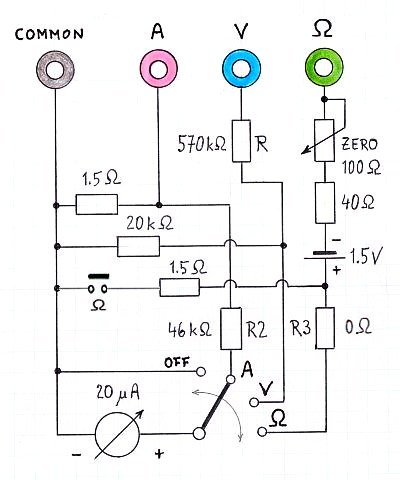 ... The "OFF" Position is used to "Short-Cut" the instrument for transportation.
Moving the instrument generates "Counter-Inductivity" what has a damping effect!
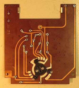
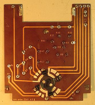
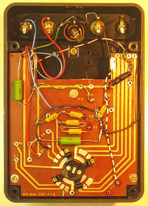
R E C Y C L I N G O F T H E E X I S T I N G P R I N T B O A R D ...
-----------------------------------------------------------------------------
TOP SIDE BACK SIDE
... The "OFF" Position is used to "Short-Cut" the instrument for transportation.
Moving the instrument generates "Counter-Inductivity" what has a damping effect!
R E C Y C L I N G O F T H E E X I S T I N G P R I N T B O A R D ...
-----------------------------------------------------------------------------
TOP SIDE BACK SIDE
  ... This is another challenge !!!
DRAWING THE S C A L E S :
--------------------------
Now the SCALES have to be drawn on white cardboard. The V & A Ranges are linear
to divide, BUT the Ω-Scale has to be found by experiment ...
... This is another challenge !!!
DRAWING THE S C A L E S :
--------------------------
Now the SCALES have to be drawn on white cardboard. The V & A Ranges are linear
to divide, BUT the Ω-Scale has to be found by experiment ...
This is the final wiring. Bottom (right) shows the battery box with contacts ...
 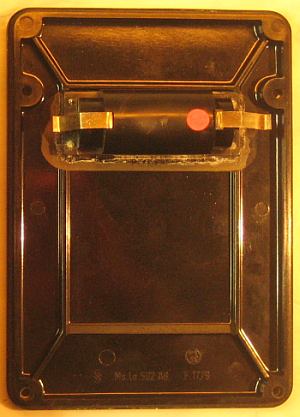 ... for the 1.5 Volt Battery, a 1/2 of a 3 Volt, eg. VARTA DUPLEX 3010
See in "FAQs" a picture of this BATTERY TYPE !!!
impressum:
***********************************************************************************
© C.HAMANN http://public.BHT-Berlin.de/hamann 07/19/12
... for the 1.5 Volt Battery, a 1/2 of a 3 Volt, eg. VARTA DUPLEX 3010
See in "FAQs" a picture of this BATTERY TYPE !!!
impressum:
***********************************************************************************
© C.HAMANN http://public.BHT-Berlin.de/hamann 07/19/12
|