previous <<==>> next
A Closer Look ...
» HOW THE TELEPHONE DIAL SYSTEM WORKS «
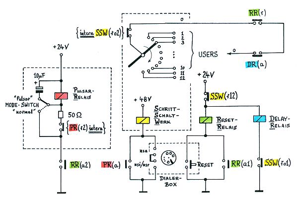
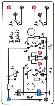
A DELAY-RELAIS added ...
... to prevent contacting users while SSW Relais is in motion.
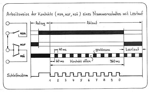
The DIALER'S PULSE-TIMING shown ...
( Diagram glued on its Back Side )
THE DIAGRAM OF THE REVISED DIAL SYSTEM ...
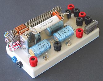
THE BUILDING BLOCKS ( with the Diagrams on its Back Sides ) ...
H O W T H E E X P E R I M E N T A L D I A L S Y S T E M W O R K S :
*****************************************************************************
RELAIS (RELAYS) and their associated CONTACTS are shown in the SAME COLOR.
where: r = "rest" Contact is closed when the relais is not activated.
a = "active" Contact is closed when the relais is activated.
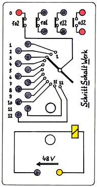
SSW(r12) opens, when the SSW ( = "Schritt-Schalt-Werk" ) reaches POSITION 12.
SSW(r02) opens, when the SSW ( = "Step-Switch-Work" ) is in motion.
SSW(r01) ( with RR(r) & DR(a), the ACTIVE TIME DELAY of DR-Relais )
ensure that NO USER CONTACT is made when the SSW is in motion.
The DIAGRAM shows an IDLE STATE with USER "3" SELECTED. To change the user,
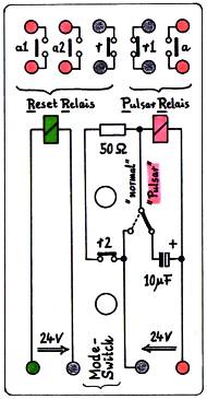
first a RESET is necessary. Pressing ( and releasing ) the RESET Button
activates the RESET-Relais, because SSW(r12) is closed. With RR(a1) it holds
its own activation and with RR(a2) it starts the PULSAR-Relais. The PULSAR-
Relais activates with PR(a) the SSW until the SSW reaches position 12 and
opens SSW(r12). This deactivates the RESET Relais and opens RR(a1) & RR(a2).
This stops the PULSAR Relais. The RESET Position is found.
Selecting (e.g.) a new USER "6" by DIALING the "6" lets the SSW move 6 steps
to position "6". After a DELAY TIME contact DR(a) connects the USER "6" ...
R E M A R K (DR) DELAY-RELAIS: S1 = T1 = ON-Delay; ( S2 = T2 = OFF-Delay )
See ... "HOW THE PULSAR IS WORKING" ... in the chapter COUNTERS.
HOW TO POWER THE EXPERIMENT with 2x24=48 Volt ?
Back to the Photo with the Building Blocks ...
IN A REAL R E L A Y D I A L S Y S T E M from 1950 (eg. DEUTSCHE POST)
"SSW"s were connected in a tree-like structure. When customer A picks up his
hand set, the 1st SSW connects customer A with the (FERNMELDEAMT in German)
SWITCHING STATION and customer A gets a DIAL TONE. When customer A dials,
every digit activates a SSW in sequence until the selected customer B is
contacted. Pulses from the SWITCHING STATION activates the RINGER in B's
station. Customer B picks up his hand set and the connection between A and B
is established. When the conversation is finished, A and B hang up and all
SSWs are RESET ...
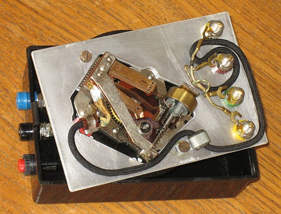
Have a look at the DEMO-VERSION of a 4x12-Step-SSW ...
|
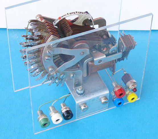 The SSW 0/12 Position-Control-Plugs LEFT ... RIGHT the SSW Power-Plugs